Monday, January 5, 2009

CCNA - Hotspot Questions

Hotspot Routing Question

hotspotquestion1a
hotspotquestion1
Question 1:
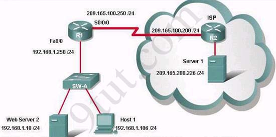
If the router R1 has a packet with a destination address 192.168.1.255, what describes the operation of the network?
A - R1 will forward the packet out all interfaces
B - R1 will drop this packet because it is not a valid IP address
C - As R1 forwards the frame containing this packet, Sw-A will add 192.168.1.255 to its MAC table
D - R1 will encapsulate the packet in a frame with a destination MAC address of FF-FF-FF-FF-FF-FF
E - As R1 forwards the frame containing this packet, Sw-A will forward it ti the device assigned the IP address of 192.168.1.255

Answer: B

Question 2:
Users on the 192.168.1.0/24 network must access files located on the Server 1. What route could be configured on router R1 for file requests to reach the server?
A - ip route 0.0.0.0 0.0.0.0 s0/0/0
B - ip route 0.0.0.0 0.0.0.0 209.165.200.226
C - ip route 209.165.200.0 255.255.255.0 192.168.1.250
D - ip route 192.168.1.0 255.255.255.0 209.165.100.250

Answer: A
Quetion 3:
When a packet is sent from Host 1 to Server 1, in how many different frames will the packet be encapsulated as it is sent across the internetwork?
A - 0
B - 1
C - 2
D - 3
E - 4

Answer: D
Question 4:
What must be configured on the network in order for users on the Internet to view web pages located on Web Server 2?
A - On router R2,configure a default static route to the 192.168.1.0 network
B - On router r2, configure DNS to resolve the URL assigned to Web Server 2 to the 192.168.1.10 address
C - On router R1, configure NAT to translate an address on the 209.165.100.0/24 network to 192.168.1.10
D - On router R1, configure DHCP to assign a registered IP address on the 209.165.100.0/24 network to Web Server 2

Answer: C
Question 5:
The router address 192.168.1.250 is the default gateway for both the Web Server 2 and Host 1. What is the correct subnet mask for this network?
A - 255.255.255.0
B - 255.255.255.192
C - 255.255.255.250
D - 255.255.255.252

Answer: A

Hotspot Frame-relay Question

hotspotquestion2
hotspotframerelay
Question 1:
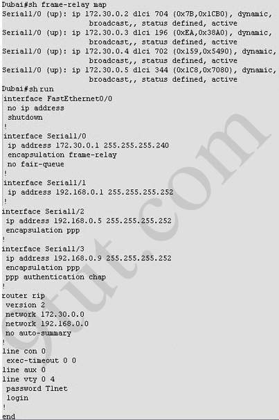
What destination Layer 2 address will be used in the frame header containing a packet for host 172.30.4.4?
A - 704
B - 196
C - 702
D - 344

Answer: C
Question 2:
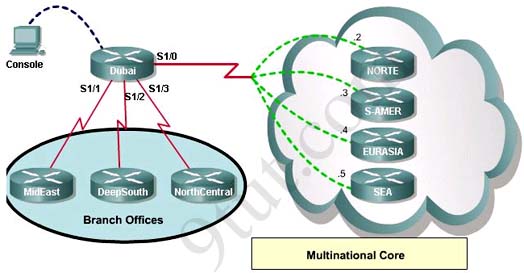
A static map to the S-AMER location is required. Which command should be used to create this map?
A - frame-relay map ip 172.30.0.3 704 broadcast
B - frame-relay map ip 172.30.0.3 196 broadcast
C - frame-relay map ip 172.30.0.3 702 broadcast
D - frame-relay map ip 172.30.0.3 344 broadcast

Answer: B
Question 3:
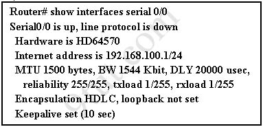
Which connection uses the default encapsulation for serial interfaces on Cisco routers?
A - The serial connection to the MidEast branch office
B - The serial connection to the DeepSouth branch office
C - The serial connection to the NorthCentral branch office
D - The serial connection to the Multinational Core

Answer: A
Question 4:
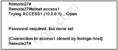
If required, what password should be configured on the router in the MidEast branch office to allow a connection to be established with the Dubai router?
A - No password is required
B - Enable
C - Scr
D - Telnet
E - Console

Answer: D

CCNA Drag and Drop Questions

Question 1:
A dental firm is redesigning the network that connects its three locations. The administrator gave the networking team 192.168.164.0 to use for addressing the entire netwok. After subnetting the address, the team is ready to assign the addresses. The administrator plans to configure ip subnet-zero and use RIP v2 as the routing protocol. As a member of the networking team, you must address the network and at the same time conserver unused addresses for future growth. With those goals in mind, drag the host addresses on the left to the correct router interface. Once of the routers is partially configured. Move your mouse over a router to view its configuration. Not all of the host addresses on the left are necessary.
vlsm1

Answer:


vlsm1_solution
Explanation:
 In short, we should start calculating from the biggest network (with 16 hosts) to the smallest one using the formula 2n - 2 (n is the number of bits we need to borrow).Therefore:
  16 hosts < 25 - 2 (we need to borrow 5 bits -> /27)
  11 hosts < 24 - 2 (borrow 4 bits -> /28)
    5 hosts < 23 - 2 (borrow 3 bits -> /29)
From the available ip addresses, we see that each of them has only one suitable solution (they are 192.168.164.149/27,192.168.164.166/28 and 192.168.164.178/29)

The smallest network is the Floss S0/0 which only requires 2 hosts = 22 - 2 (need to borrow 2 bits ->/30). There are 2 suitable answers: 192.168.164.189/30 and 192.168.164.188/30 but notice that 192.168.164.188/30 is the network address so we can not use it (because 188 = 4 * 47) -> we have to choose 192.168.164.189 as the correct solution.
In fact, it is not the formal way to solve a VLSM question so I recommend you to review your CCNA book if you haven't grasped it well yet.

Question 2:
In order to complete a basic switch configuration, drag each switch IOS command on the left to its purpose on the right

commanddragdrop


Answer:
1) enable
2) configure terminal
3) hostname
4) Interface vlan 1
5) no shutdown
6) ip address
7) ip default-gateway

Question 3:
The Missouri branch office router is connected through its s0 interface to the Alabama Headquarters router s1 interface. The Alabama router has two LANs. Missouri users obtain Internet access through the Headquarters router. The network interfaces in the topology are addressed as follows: Missouri: e0 - 192.168.35.17/28; s0 - 192.168.35.33/28; Alabama: e0 - 192.168.35.49/28; e1 - 192.168.35.65/28; s1 - 192.168.35.34/28. The accounting server has the address of 192.168.35.66/28. Match the access list conditions on the left with the goals on the right. (Not all options on the left are used.)

accesslist1


Answer:
1) deny ip 192.168.35.16 0.0.0.15 host 192.16.35.66
2) deny ip 192.168.35.55 0.0.0.0 host 192.168.35.66
3) permit ip 192.168.35.0 0.0.0.255 host 192.168.35.66

Question 4:
A host with the address of 192.168.125.34/27 needs to be denied access to all hosts outside its own subnet. To accomplish this, complete the command in brackets, [access-list 100 deny protocol address mask any], by dragging the appropriate options on the left to their correct placeholders on the right.

accesslist2


Answer:
1) ip
2) 192.168.125.34
3) 0.0.0.0
Full command: access-list 100 deny ip 192.168.125.34 0.0.0.0

Question 5:
Drag and drop the network user application to the appropriate description of its primary use (not all options are used)

networkapplication


Answer:
1) web browser
2) instant message
3) e-mail
4) database
5) collaboration

Question 6:
This topology contains 3 routers and 1 switch. Complete the topology.

Drag the appropriate device icons to the labeled Device
Drag the appropriate connections to the locations labeled Connections.
Drag the appropriate IP addresses to the locations labeled IP address
(Hint: use the given host addresses and Main router information)
To remove a device or connection, drag it away from the topology.
Use information gathered from the Main router to complete the configuration of any additional routers. No passwords are required to access the Main router . The config terminal command has been disabled for the HQ router. The router does not require any configuration.

Configure each additional router with the following

Configure the interfaces with the correct IP address and enable the interfaces.
Set the password to allow console access to consolepw
Set the password to allow telnet access to telnetpw
Set the password to allow privilege mode access to privpw
Note: Because routes are not being added to the configurations, you will not be able to ping through the internetwork.
All devices have cable autosensing capabilities disabled.
All hosts are PC’s

assigncableandip


Answer:
networkapplication_solution

CCNA Implementation SIM

(Updated from real CCNA exam on 12-20-2008)
This topology contains 3 routers and 1 switch. Complete the topology.
Drag the appropriate device icons to the labeled Device
Drag the appropriate connections to the locations labeled Connections.
Drag the appropriate IP addresses to the locations labeled IP address

(Hint: use the given host addresses and Main router information)
To remove a device or connection, drag it away from the topology.
Use information gathered from the Main router to complete the configuration of any additional routers. No passwords are required to access the Main router. The config terminal command has been disabled for the HQ router. The router does not require any configuration.

Configure each additional router with the following:
Configure the interfaces with the correct IP address and enable the interfaces.
Set the password to allow console access to consolepw
Set the password to allow telnet access to telnetpw
Set the password to allow privilege mode access to privpw
Note: Because routes are not being added to the configurations, you will not be able to ping through the internetwork.
All devices have cable autosensing capabilities disabled.
All hosts are PC’s
Answer and explanation:


Specify appropriate devices and drag them on the "Device" boxes
For the device at the bottom-right box, we notice that it has 2 interfaces Fa0/2 and Fa0/4 -> it is a switch
The question stated that this topology contains 3 routers and 1 switch -> two other devices are routers
Place them on appropriate locations as following:

ccna_implementation_1
(Host D and host E will be automatically added after placing two routers. Click on them to access neighboring routers)
Specify appropriate connections between these devices:
+ The router on the left is connected with the Main router through FastEthernet interfaces: use a crossover cable
+ The router on the right is connected with the Main router through Serial interfaces: use a serial cable
+ The router on the right and the Switch: use a straight-through cable
+ The router on the left and the computer: use a crossover cable

ccna_implementation_2
Assign appropriate IP addresses for interfaces:
From Main router, use show running-config command:

ccna_implementation_3
(Notice that you may see different IP addresses in the real CCNA exam, the ones shown above are just used for demonstration)
From the output we learned that the ip address of Fa0/0 interface of the Main router is 192.168.152.178/28. This address belongs to a subnetwork which has:
Increment: 16 (/28 = 255.255.255.240 or 1111 1111.1111 1111.1111 1111.1111 0000)
Network address: 192.168.152.176 (because 176 = 16 * 11 and 176 < 178)
Broadcast address: 192.168.152.191 (because 191 = 176 + 16 - 1)
And we can pick up an ip address from the list that belongs to this subnetwork: 192.168.152.190 and assign it to the Fa0/0 interface the router on the left
Use the same method for interface Serial0/0 with an ip address of 192.168.152.172
Increment: 16
Network address: 192.168.152.160 (because 160 = 16 * 10 and 160 < 172)
Broadcast address: 192.168.152.175 (because 176 = 160 + 16 - 1)
-> and we choose 192.168.152.174 for Serial0/0 interface of the router on the right

Interface Fa0/1 of the router on the left
IP (of the computer on the left) : 192.168.152.129/28
Increment: 16
Network address: 192.168.152.128 (because 128 = 16 * 8 and 128 < 129)
Broadcast address: 192.168.152.143 (because 143 = 128 + 16 - 1)
-> we choose 192.168.152.142 from the list

Interface Fa0/0 of the router on the right
IP (of the computer on the left) : 192.168.152.225/28
Increment: 16
Network address: 192.168.152.224 (because 224 = 16 * 14 and 224 < 225)
Broadcast address: 192.168.152.239 (because 239 = 224 + 16 - 1)
-> we choose 192.168.152.238 from the list Let's have a look at the picture below to summarize

ccna_implementation_4
Configure two routers on the left and right with these commands:
Router1 = router on the left
Assign appropriate IP addresses to Fa0/0 & Fa0/1 interfaces:
Router1>enable
Router1#configure terminal
Router1(config)#interface fa0/0
Router1(config-if)#ip address 192.168.152.190 255.255.255.240
Router1(config-if)#no shutdown
Router1(config-if)#interface fa0/1
Router1(config-if)#ip address 192.168.152.142 255.255.255.240
Router1(config-if)#no shutdown
Set passwords (configure on two routers)
+ Console password:
Router1(config-if)#exit
Router1(config)#line console 0
Router1(config-line)#password consolepw
Router1(config-line)#login
Router1(config-line)#exit
+ Telnet password:
Router1(config)#line vty 0 4
Router1(config-line)#password telnetpw
Router1(config-line)#login
Router1(config-line)#exit
+ Privilege mode password:
Router1(config)#enable password privpw

Save the configuration:
Router1(config)#exit
Router1#copy running-config startup-config
Configure IP addresses of Router2 (router on the right)
Router2>enable
Router2#configure terminal
Router2(config)#interface fa0/0
Router2(config-if)#ip address 192.168.152.238 255.255.255.240
Router2(config-if)#no shutdown

Router2(config-if)#interface serial0/0
Router2(config-if)#ip address 192.168.152.174 255.255.255.240
Router2(config-if)#no shutdown
and set console, telnet and privilege mode passwords for Router2 as we did for Router1, remember to save the configuration when you finished

CCNA Troubleshooting Questions 2

Question 1:
A network administrator is troubleshooting the OSPF configuration of routers R1 and R2. The routers cannot establish an adjacency relationship on their common Ethernet link. The graphic shows the output of the show ip ospf interface e0 command for routers R1 and R2. Based on the information in the graphic, what is the cause of this problem?
showipospfinterface
A. The OSPF area is not configured properly.
B. The priority on R1 should be set higher.
C. The cost on R1 should be set higher.
D. The hello and dead timers are not configured properly.
E. A backup designated router needs to be added to the network.
F. The OSPF process ID numbers must match.

Answer: D


Question 2:
This graphic shows the results of an attempt to open a Telnet connection to router ACCESS1 from router Remote27. Which of the following command sequences will correct this problem?
telnet
A. ACCESS1(config)# line console 0
ACCESS1(config-line)# password cisco
B. Remote27(config)# line console 0
Remote27(config-line)# login
Remote27(config-line)# password cisco
C. ACCESS1(config)# line vty 0 4
ACCESS1(config-line)# login
ACCESS1(config-line)# password cisco
D. Remote27(config)# line vty 0 4
Remote27(config-line)# login
Remote27(config-line)# password cisco
E. ACCESS1(config)# enable password cisco
F. Remote27(config)# enable password cisco


Answer: C


Question 3:
Refer to the exhibit. A network administrator attempts to ping Host2 from Host1 and receives the results that are shown. What is a possible problem?
ping
A. The link between Host1 and Switch1 is down.
B. TCP/IP is not functioning on Host1
C. The link between Router1 and Router2 is down.
D. The default gateway on Host1 is incorrect.
E. Interface Fa0/0 on Router1 is shutdown.
F. The link between Switch1 and Router1 is down.


Answer: C


Question 4:
Refer to the exhibit. Hosts in network 192.168.2.0 are unable to reach hosts in network 192.168.3.0. Based on the output from RouterA, what are two possible reasons for the failure? (Choose two)
showipinterfacebrief
A. The cable that is connected to S0/0 on RouterA is faulty.
B. Interface S0/0 on RouterB is administratively down.
C. Interface S0/0 on RouterA is configured with an incorrect subnet mask.
D. The IP address that is configured on S0/0 of RouterB is not in the correct subnet.
E. Interface S0/0 on RouterA is not receiving a clock signal from the CSU/DSU.
F. The encapsulation that is configured on S0/0 of RouterB does not match the encapsulation that is configured on S0/0 of RouterA.


Answer: E F


Question 5:
When upgrading the IOS image, the network administrator receives the exhibited error message. What could be the cause of this error?
copytftpflash
A. The new IOS image is too large for the router flash memory.
B. The TFTP server is unreachable from the router.
C. The new IOS image is not correct for this router platform.
D. The IOS image on the TFTP server is corrupt.
E. There is not enough disk space on the TFTP server for the IOS image.


Answer: B

CCNA Troubleshooting Questions 1

Question 1:
Refer to the exhibit. The network administrator is in a campus building distant from Building B. WANRouter is hosting a newly installed WAN link on interface S0/0. The new link is not functioning and the administrator needs to determine if the correct cable has been attached to the S0/0 interface. How can the administrator accurately verify the correct cable type on S0/0 in the most efficient manner?
remoteconnect1
A. Telnet to WANRouter and execute the command show interfaces S0/0
B. Telnet to WANRouter and execute the command show processes S0/0
C. Telnet to WANRouter and execute the command show running-configuration
D. Telnet to WANRouter and execute the command show controller S0/0
E. Physically examine the cable between WANRouter S0/0 and the DCE.
F. Establish a console session on WANRouter and execute the command show interfaces S0/0

Answer: D


Explanation:
The show controller command displays the information about the physical interface itself and the type of serial cable plugged into a serial port. In this case, it should be a DTE cable that plugs into a type of data service unit (DSU).
For your understanding, below is the output of this command:

show_controllers
From the output, we notice that serial 0/0 has a DTE cable and would get its clocking from the DSU.

Question 2:
Two routers named Atlanta and Brevard are connected by their serial interfaces as shown in the exhibit, but there is no data connectivity between them. The Atlanta router is known to have a correct configuration. Given the partial configurations shown in the exhibit, what is the problem on the Brevard router that is causing the lack of connectivity?

connecttworouters
A. A loopback is not set
B. The IP address is incorrect.
C. The subnet mask is incorrect.
D. The serial line encapsulations are incompatible.
E. The maximum transmission unit (MTU) size is too large.
F. The bandwidth setting is incompatible with the connected interface.


Answer: B


Question 3:
Refer to the exhibit. The two exhibited devices are the only Cisco devices on the network. The serial network between the two devices has a mask of 255.255.255.252. Given the output that is shown, what three statements are true of these devices? (Choose three)

showcdptworouters
A. The Manchester serial address is 10.1.1.1.
B. The Manchester serial address is 10.1.1.2.
C. The London router is a Cisco 2610.
D. The Manchester router is a Cisco 2610.
E. The CDP information was received on port Serial0/0 of the Manchester router.
F. The CDP information was sent by port Serial0/0 of the London router.


Answer: A C E


Question 4:
A network administrator has configured two switches, named London and Madrid, to use VTP. However, the switches are not sharing VTP messages. Given the command output shown in the graphic, why are these switches not sharing VTP messages?

showvtp
A. The VTP version is not correctly configured.
B. The VTP operating mode is not correctly configured.
C. The VTP domain name is not correctly configured.
D. VTP pruning mode is disabled.
E. VTP V2 mode is disabled.
F. VTP traps generation is disabled.


Answer: C


Question 5:
The network shown in the diagram is experiencing connectivity problems. Which of the following will correct the problems? (Choose two.)

vlansetup
A. Configure the gateway on Host A as 10.1.1.1.
B. Configure the gateway on Host B as 10.1.2.254.
C. Configure the IP address of Host A as 10.1.2.2.
D. Configure the IP address of Host B as 10.1.2.2.
E. Configure the masks on both hosts to be 255.255.255.224.
F. Configure the masks on both hosts to be 255.255.255.240.


Answer: B D
Question 6:
Refer to the exhibit:

intervlan1
The network administrator has created a new VLAN on Switch1 and added host C and host D. The administrator has properly configured switch interfaces FastEthernet0/13 through FastEthernet0/24 to be members of the new VLAN. However, after the network administrator completed the configuration, host A could communicate with host B, but host A could not communicate with host C or host D. Which commands are required to resolve this problem?
A. Router(config)# interface fastethernet 0/1.3
Router(config-if)# encapsulation dot1q 3
Router(config-if)# ip address 192.168.3.1 255.255.255.0
B. Router(config)# router rip
Router(config-router)# network 192.168.1.0
Router(config-router)# network 192.168.2.0
Router(config-router)# network 192.168.3.0
C. Switch1# vlan database
Switch1(vlan)# vtp v2-mode
Switch1(vlan)# vtp domain cisco
Switch1(vlan)# vtp server
D. Switch1(config)# interface fastethernet 0/1
Switch1(config-if)# switchport mode trunk
Switch1(config-if)# switchport trunk encapsulation isl


Answers: A


Question 7:
Refer to the exhibit. Hosts on the same VLAN can communicate with each other but are unable to communicate with hosts on different VLANs. What is needed to allow communication between VLANs?

intervlan2
A. a switch with a trunk link that is configured between the switches
B. a router with an IP address on the physical interface that is connected to the switch
C. a switch with an access link that is configured between the switches
D. a router with subinterfaces configured on the physical interface that is connected to the switch


Answer: D


Question 8:
The show interfaces serial 0/0 command resulted in the output shown in the graphic. What are possible causes for this interface status? (Choose three)

showinterfaces
A. The interface is shut down.
B. No keepalive messages are received.
C. The clockrate is not set.
D. No loopback address is set.
E. No cable is attached to the interface.
F. There is a mismatch in the encapsulation type.


Answer: B C F
Question 9:
While troubleshooting a connectivity issue from a PC you obtain the following information:
Local PC IP address: 10.0.0.35/24
Default Gateway: 10.0.0.1

Remote Sever: 10.5.75.250/24
You then conduct the following tests from the local PC:
Ping 127.0.0.1 - Successful
Ping 10.0.0.35 - Successful
Ping 10.0.0.1 - Unsuccessful
Ping 10.5.75.250 - Unsuccessful

troubleshootingconnectivity
What is the underlying cause of this problem?
A. A remote physical layer problem exists.
B. The host NIC is not functioning.
C. TCP/IP has not been correctly installed on the host.
D. A local physical layer problem exists.


Answer: D